Tutorial Labview Basics II - Temperature & Control 2
INTRODUCTION
In this tutorial, you will open the last tutorial and add a temperature threshold control and an over temperature indicator to the VI. To achieve this, you will:
-
Start Labview, Open the Temperature Control VI and "Save As"
-
Add a Digital Control to the Front Panel and Rename It
-
Add a Round LED Indicator to the Front Panel and Rename It
-
Add a Great? Function to the Diagram
-
Wire Everything Together in the Block Diagram
-
Run the VI and Observe the Results
-
Save the VI and Exit Labview
START LABVIEW, OPEN THE TEMPERATURE CONTROL VI AND SAVE-AS
Start Labview
Click on Open VI  in the Labview Splash Screen in the Labview Splash Screen
Locate and open the Temperature_Control_1.vi
Arrange the Front Panel and Diagram windows left and right with the Tile left and Right command
Click on File pull down and Save as
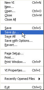
Save as to Temperature_Control_2.vi
Show the Tools Palette
ADD A DIGITAL CONTROL TO THE FRONT PANEL AND RENAME IT
Right-Click on the Front Panel Window
You should see the Controls Palette
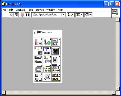
Bring the cursor over the Numeric button (Upper Left)
The Numeric Menu should appear
Bring the cursor over the Digital Control> Left-Click on the selection and drag the control onto the Control Panel just to the upper-left left of the Temperature Control
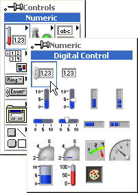
Rename its label to Threshold
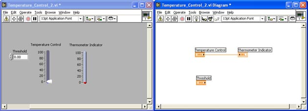
In the Diagram window, drag the Threshold Digital Control under the Temperature Control
Your Control Panel and Block Diagram should look like this:
ADD A ROUND LED INDICATOR TO THE FRONT PANEL AND RENAME IT
Right-Click on the Front Panel Window
The Numeric Menu should appear
Bring the cursor over the Boolean button
The Boolean Menu should appear
Bring the cursor over the Round LED > Left-Click on the selection and drag the control onto the Front Panel just below the Threshold Control
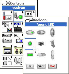
Rename its label to Overtemp
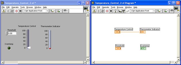
Move the Round LED Indictor's terminal to just below the Thermometer Indicator's terminal in the Block Diagram Window
Your Control Panel and Block Diagram should look like this:
ADD A GREATER? FUNCTION TO THE DIAGRAM
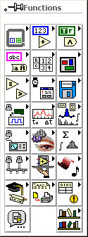
Right-Click in the Block Diagram Window
The Function Palette should appear:
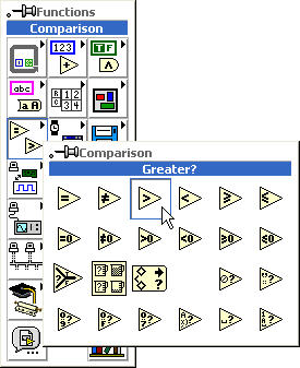
Bring the cursor over the Comparison Button
The Comparison Sub-Menu should Appear
Bring the cursor over the Greater? Function > Left-Click on the selection and drag the function onto the Block Diagram in the middle between the other nodes.
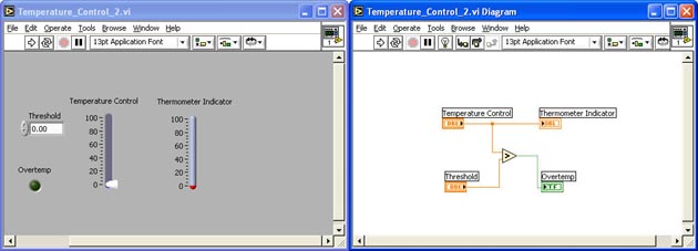
Your Control Panel and Block Diagram should look like this:

WIRE EVERYTHING TOGETHER IN THE BLOCK DIAGRAM
In the Block Diagram Window, Wire the Threshold terminal to lower input terminal of the the Greater? function
Wire the output terminal of the Greater? function to the Overtemp terminal
Wire the upper input terminal of the Greater? function to the existing wire between the Temperature Control and Thermometer Indicator terminals. This will create a wire junction
Note: The existing wire should blink indicating that a good junction will be created
Your Control Panel and Block Diagram should look like this:
RUN THE VI AND OBSERVE THE RESULTS
In the Control Panel window, Change the threshold value to 50
Run the VI Continuously
Move the Slider on the Temperature Control and note when the Overtemp LED
Experiment with different threshold values
Stop the VI
SAVE THE VI AND EXIT LABVIEW
|