FIGURE 1
Introduction: Polymer electrolyte fuel
cells ( PEFCs) have attracted much interest recently. The need for an efficient,
non-polluting power source for vehicles in urban environments, emphasized by
recent legislative initiatives, has resulted in increased attention to the
option of fuel-cell powered vehicles of high efficiency and low tail pipe
emissions. Hydrogen is the most suitable fuel for a fuel cell powered vehicle,
providing the highest conversion efficiency for fuel-on-board-to-electric-power
and generating zero tail-pipe emission since water is the only product of the
hydrogen/air fuel cell process. Hydrogen fuel could be carried on board the
vehicle as either neat hydrogen, in the form of pressurized gas or cryogenically
stored liquid, or in the form of a more ordinary liquid fuel, such as methanol
or liquid hydrocarbon, which needs to be processed/converted on board the
vehicle to a mixture of hydrogen and CO2. The latter type of vehicle
will not satisfy the criteria of a ìZero-Emission-Vehicleî ( ZEV), but may still
satisfy the criteria for an Ultra Low Emission Vehicleî ( ULEV).
Of various fuel cell systems considered, the polymer electrolyte fuel cell
technology seems to be most suitable for terrestrial transportation
applications. This is thanks to low temperature of operation ( hence, fast cold
start) , perfect CO2 tolerance by the electrolyte and a combination
of high power density and high energy conversion efficiency. Key barriers for
the development of this fuel cell technology for terrestrial applications,
considered very high just 5-10 years ago, have been successfully overcome. As a
result, automotive and fuel cell manufacturing industries have initiated
significant technology validation programs and demonstrations which include fuel
cell powered vehicles, stationary power generation systems and battery
replacement devices. Market entry of PEFCs through the latter applications may
actually precede implementation of such fuel cells in vehicular power systems,
in large part because of less stringent demands on systemís cost.
In this Mini-Workshop, we will show how novel materials and the R&D
efforts towards their characterization and development, have advanced PEFC
performance, lowered cost and enhanced reliability and, consequently, enabled
the significant recent advancements in this fuel cell technology.
We specifically discuss the following subjects:
(1) The Polymer Electrolyte Fuel Cell -- general description
(2) Catalysts and the Membrane/Electrode Assembly
(3) The Ionomeric Membrane
(4) Carbon and Metal Hardware Components for Gas Distribution and Current
Collection
The Polymer Electrolyte Fuel Cell: General Description: We give first a general description of the polymer electrolyte fuel cell, highlighting central issues of Materials requirements for this unique Hydrogen fueled power source. In the text, we highlight materials to be discussed by using italics.
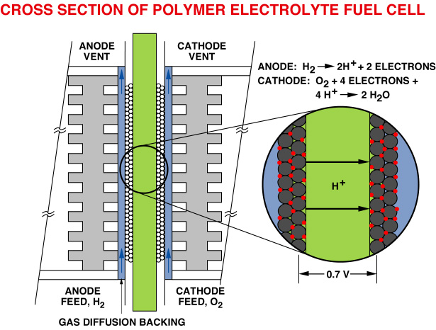
FIGURE 1
Figure 1 is a schematic presentation of the cross-section of a single polymer electrolyte fuel cell ( PEFC). This scheme will be used to discuss the key materials and processes in the PEFCs. The "heart" of the cell, which is magnified in the scheme, is the so-called membrane-electrode ( M&E) assembly. In it's simplest form, the "electrode" component of the M&E assembly would be a thin film ( 5-50 mm thick ) containing dispersed Pt catalyst. This catalyst layer is in good contact with an ionomeric membrane, the central slab in the scheme in figure 1, which serves as the electrolyte and the gas separator in the cell. The ionomeric membrane electrolyte is typically 50-175 mm thick.
A so-called M&E assembly thus consists of an ionomeric membrane with thin catalyst layers bonded onto each of it's two major surfaces. It can be seen that the M&E assembly has the generic structure of an electrochemical cell: electrode/electrolyte/electrode, packaged in the form of a ìsandwichî of three thin films. The "gas-diffuser"
( or "backing" ) layers in immediate contact with the catalyzed membrane ( see fig.1) are made of hydrophobized porous carbon paper, or carbon cloth. These layers are typically 100-300 mm thick and are wet-proofed by treatment with poly-tetrafluoroethylene (PTFE). The role of these gas diffusers is to enable direct and uniform access of the reactant gases, hydrogen and oxygen, to the catalyst layers, without having to diffuse through films of liquid water.
The single cell is completed by current collector plates which usually contain machined flow fields, as required for effective distribution of reactant gases along the surfaces of the electrodes. These plates, traditionally made of high density graphite, become ìbipolar platesî in the fuel cell stack, in which case they would have gas flow fields on both sides, as shown schematically in Figure 1. A general view of a single cell hardware is presented in Figure 2. The Teflon masks shown are gaskets that confine the gas flow to the active area and provide, together with the periphery of the ionomeric membrane, an effective seal. In a fuel cell stack, many such cells are stacked together to generate the voltage required for a given application, since a single hydrogen/oxygen fuel cell operated at only about 0.7V.
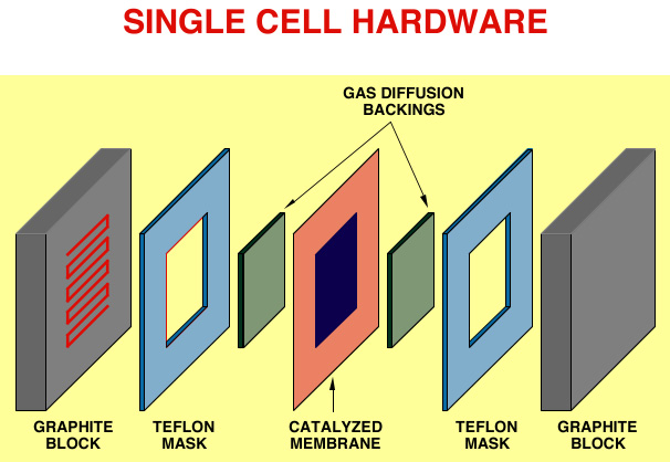
FIGURE 2
The above short discussion of the unit cell of a polymer electrolyte fuel cell stack, highlights different materials of unique characteristics ( see italicized materials & components names) , required to achieve a fuel cell power source of high performance, high energy conversion efficiency and stable long-term operation. We discuss them further below.
Electrocatalysts: Returning to the M&E assembly, the
magnified part in Figure 1 highlights the central element of the PEFC which
consists of a proton-conducting membrane electrolyte with a composite catalyst
layer adjacent to each of it's surfaces. The scheme shows the catalyst layer as
Pt ( small circles) supported on carbon ( larger circles). This type of catalyst
has been used in more recent developments of PEFCs. The Pt/C powder,
prepared mostly by procedures based on colloid chemistry consists of Pt
particles about 2 nm in diameter, supported on carbon particles about 10 nm in
diameter. Pt is an essential catalyst for the electrochemical conversion
of hydrogen and oxygen at the anode and cathode of the fuel cell, respectively,
into electric current ( electric power). In the hydrogen/air fuel cell, the
processes at the anode and cathode, respectively, are:
and,
The Pt/C powder has to be intimately intermixed with recast ionomer to
provide sufficient ionic conductivity within the catalyst layer. Thus, the
catalyst layer can be described as a Pt/C//ionomer composite, where each
of the three components are uniformly distributed within the volume of the
layer. PEFC stacks fabricated at this point still use PTFE-bonded Pt black
catalysts applied by hot-press to the ionomeric membrane. Such Pt-black- based
catalyst layers typically require a Pt loading 20-40 times higher than that
required in the Pt/C catalyst ( 4mgPt/cm2 vs. 0.1 mg
Pt/cm2) to obtain a similar cell performance. Pt/C catalysts
will have to be adapted in commercial PEFCs because of their much lower cost and
their intrinsic high performance and reliability. Work at LANL during the last
five years has brought the low-Pt- loading M&E technology to the point of
industrial realization, enabling an important lowering of the cost barrier to
implementation of polymer electrolyte fuel cell technology.
The Ionomeric Membrane: The proton conducting polymeric membrane is the most unique element of the polymer electrolyte fuel cell, as indeed reflected by any of the three names used for this type of cell: PEM fuel cell = Polymer Electrolyte Membrane fuel cell, SPETM fuel cell = Solid Polymer Electrolyte Fuel Cell, or PEFC = Polymer Electrolyte Fuel Cell. The membrane commonly employed in most recent PEFC technology developments is made of a perfluorocarbon sulfonic acid ionomer. NafionTM made by DuPont is the most well known material of this type. Similar materials are produced as either commercial or developmental products by W.L. Gore ( US), Asahi Chemical and Asahi Glass ( Japan). The combined chemical and physical properties of perfluorocarbon sulfonate ( PFSA) membranes give them significant superiority over any other membrane material as electrolytic separators in PEFCs. These membranes exhibit very high long-term chemical stability under both oxidative and reductive environments, thanks to their Teflon-like molecular backbone. The protonic conductivities achieved in well humidified membranes are as high as 0.1 S/cm at cell operation temperatures, which translates to an ìareal resistanceî as low as 0.05 ohm cm2 for a membrane 50 mm thick. Such a thin membrane can serve at the same time as an effective gas separator: the permeability of both oxygen and hydrogen through the membrane are both of the order of 10-11 -10-10 mol/cm-sec-atm, which translates to a gas cross-over equivalent current density of 1-10 mA/cm2 through a 100 mm thick membrane in an operating fuel cell. This leakage current is at or below 1% of the operating current of a PEFC -- typically 1A/cm2 or higher.
The two important drawbacks of PFSA membranes are the limited range of
temperatures in which they can be effectively employed and their high cost at
present. The first limitation typically forces operation of PEFCs at
temperatures below 1000C, although some increase of the
temperature of operation, e.g., to 1200C, may be possible at
the expense of operation under pressurized steam. The upper limit on the
temperature is dictated by the need of effective humidification of the membrane,
a prerequisite for maximizing the protonic conductivity in it. This need also
dictates, in turn, operation in a temperature/pressure domain corresponding to a
dual phase (liquid-vapor) water system, which results in liquid water removal
and/or liquid water recirculation requirements. The cost of the membrane is an
issue outside the scope of our discussion. However, it can be predicted with
reasonable certainty that this cost may come down significantly as the market
for the membrane will significantly increase , e.g., as a result of large scale
application in electric vehicles.
The Gas Diffuser: The porous backing layer which is
placed behind the catalyst layer ( figure 1) fulfills important tasks in the
PEFC. In this layer, combined requirements of effective reactant gas supply to
the catalyst layer and effective water supply and removal in either vapor or
liquid form have to be simultaneously fulfilled. Wet-proofing by PTFE is
required to ensure that at least part of the pore volume in the cathode backing
remains free of liquid water in an operating cell, so as to enable rapid
gas-phase transport. The scale of the porosity and the amount of PTFE added are
two important parameters that determine the success of the backing layer in
fulfilling the combined tasks of gas and water transport. Obviously, the backing
layer has to be made of a material of high and stable electronic conductivity in
a wet environment. Although some expanded metal structures have been suggested,
most of PEFC backings to date have been based on porous carbon paper or cloth.
Graphite vs. Metal Hardware for Gas Distribution/Current
Collection: The final element on the outer side of the unit cell (
figures 1 and 2) is the current collector plate which typically contains a
machined gas flow field. These two functions of current collector and gas flow
field may be fulfilled, in principle, by two separate components but , in most
of the cells and stacks tested to date the flow field is machined in the current
collector plate using a range of geometries, e.g., a single serpentine channel,
parallel channel flow and series-parallel combinations. The flow-field geometry
may be quite significant in fulfilling the requirements of effective water
supply and effective liquid water removal from the cathode. The current
collector plate becomes the bipolar plate in a PEFC stack. It should therefore
exhibit high electronic conductivity and be impermeable to oxygen and hydrogen
gas. Both carbon and metals like stainless steel or titanium have been
considered as potential materials for the current collector, or bipolar plate as
it would be called in the context of a stack.
The very general description provided above for the component parts of a PEFC should clarify the diversity of R&D elements involved in the development of a PEFC cell and stack. These R&D elements span fields of research in interfacial electrochemistry
( electrocatalysis), electrochemistry and materials science aspects of
membranes, carbon and metals, and mass/ heat transport engineering. This
Workshop covers some highlights of LANL work on electrochemical and materials
aspects of the PEFC as well as the building and testing of cells based on
improved materials and electrocatalysts. In most general terms, the target of
these efforts in development of materials and components has been to achieve
high PEFC performance, long-term performance stability and low intrinsic cost.